
Description
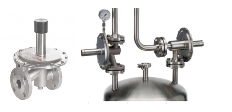
Nitrogen blanketing regulators, also known as inert gas regulators, are devices used to control and regulate the flow and pressure of nitrogen gas used for blanketing or inerting purposes. Nitrogen blanketing is a technique commonly employed in various industries to protect sensitive materials or processes from exposure to oxygen or other reactive gases.
The primary purpose of nitrogen blanketing is to create a layer of inert gas (nitrogen) on top of a liquid or within a vessel or storage tank. This inert gas layer acts as a barrier, preventing the entry of oxygen or other contaminants that could react with or deteriorate the stored material or affect the process.
The nitrogen blanketing regulator typically consists of the following components:
1. Inlet Connection : This is the point where the nitrogen gas supply is connected to the regulator.
2. Pressure Control Knob : The pressure control knob allows the user to adjust the desired pressure level of the nitrogen gas.
3. Pressure Gauge : The pressure gauge displays the pressure of the nitrogen gas within the system, enabling the user to monitor and maintain the desired pressure range.
4. Outlet Connection : The outlet connection is where the regulated nitrogen gas is supplied to the blanketing system, vessel, or storage tank.
5. Safety Relief Valve : A safety relief valve is incorporated to prevent over-pressurization of the system. It releases excess pressure if the pressure exceeds the set limit, ensuring the safe operation of the equipment.
6. Flow Control : Some nitrogen blanketing regulators may have a flow control mechanism that allows users to adjust the flow rate of the nitrogen gas.
Breather Valves
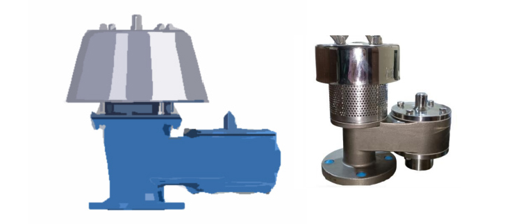
A breather valve, also known as a pressure/vacuum relief valve or a conservation vent, is a safety device commonly used in storage tanks, vessels, or other enclosed systems to prevent the buildup of excessive pressure or vacuum conditions.
The primary function of a breather valve is to maintain the desired pressure range within the storage tank or vessel, ensuring the structural integrity and safe operation of the system. It achieves this by allowing the controlled release of excess pressure or the ingress of air during vacuum conditions.
Here are the key components and features of a typical breather valve :
1. Valve Body : The valve body is the main housing of the breather valve, typically made of metal or composite materials. It houses the internal components and provides the necessary sealing to prevent gas leakage.
2. Pressure Relief Section : This section of the breather valve is responsible for relieving excess pressure within the tank or vessel. It consists of a pressure relief disk or pallet, which is designed to lift or open when the pressure exceeds the set limit. This allows the excess pressure to escape to the atmosphere.
3. Vacuum Relief Section : The vacuum relief section is designed to prevent the creation of a vacuum inside the tank or vessel. It consists of a vacuum relief disk or pallet that opens when a vacuum condition occurs, allowing air to enter and equalize the pressure.
4. Hinge Mechanism : The pressure and vacuum relief disks are typically attached to the valve body through a hinge mechanism. This allows them to move freely and respond to pressure or vacuum conditions.
5. Spring or Weight : A breather valve may incorporate a spring or weight mechanism to provide the required force for keeping the pressure relief and vacuum relief disks in the closed position. The spring or weight is calibrated to open the valve at the predetermined pressure or vacuum levels.
6. Screen or Filter : Some breather valves include a screen or filter element to prevent the ingress of dust, particles, or insects into the tank or vessel during pressure or vacuum relief.
Flame Arrestors
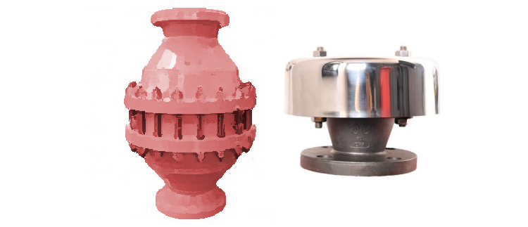
A flame arrester, also known as a flame arrestor or deflagration arrester, is a safety device designed to prevent the propagation of flames or explosions in a piping system or equipment where flammable gases or vapors are present. It is commonly used in various industries, such as oil and gas, chemical, and pharmaceutical, to mitigate the risks associated with the ignition of flammable substances.
The primary function of a flame arrester is to allow the flow of gases or vapors through a system while preventing the passage of flames or explosions. It consists of a housing or casing that contains a flame-quenching element, typically made of metal or other heat-conductive materials. The flame-quenching element is designed to absorb and dissipate the heat from a flame, disrupting its propagation and preventing it from reaching the flammable mixture on the other side of the arrester.
Here are the key components and features of a typical flame arrester :
1. Housing/Casing : The housing or casing of a flame arrester is usually made of a durable and heat-resistant material, such as stainless steel or cast aluminum. It provides structural support and contains the internal components.
2. Flame-Quenching Element : This is the crucial component of the flame arrester that extinguishes and quenches the flame. It is typically a metal matrix or wire mesh, arranged in a way that allows the flow of gases or vapors while providing a tortuous path for the flame. The flame-quenching element is designed to absorb heat and conduct it away from the flame, reducing its temperature below the ignition point.
3. Inlet and Outlet Ports : The flame arrester has an inlet port where the flammable gases or vapors enter and an outlet port through which the treated gases or vapors exit. The ports are designed to ensure proper alignment and connection with the piping system.
4. Mounting Flange : Many flame arresters have a mounting flange that allows them to be securely attached to the piping system or equipment.
5. Maintenance/Inspection Port : Some flame arresters include a maintenance or inspection port that allows access to the internal components for cleaning, inspection, or maintenance purposes.
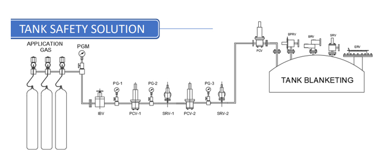
High Pressure N2/H2 Pressure Reducing Stations
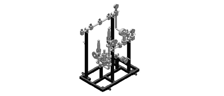
A high-pressure nitrogen pressure reducing station, also known as a nitrogen pressure regulator station, is a system used to reduce the high pressure of nitrogen gas to a lower, more manageable pressure for specific applications or downstream equipment. These stations are commonly employed in industries such as oil and gas, chemical, and manufacturing, where high-pressure nitrogen is utilized for various purposes.
Here are the key components and features typically found in a high-pressure nitrogen pressure reducing station :
1. Inlet Connection : This is the point where the high-pressure nitrogen gas supply is connected to the pressure reducing station.
2. High-Pressure Regulator : The high-pressure regulator is a critical component that controls and reduces the pressure of the incoming nitrogen gas. It is designed to handle the high-pressure conditions and ensure a consistent and stable output pressure.
3. Pressure Gauge : A pressure gauge is installed to monitor and display the pressure of the nitrogen gas within the system. It provides valuable information to operators and allows them to verify that the desired pressure range is being maintained.
4. Pressure Relief Valve : A pressure relief valve acts as a safety device to protect the system from over-pressurization. It releases excess pressure if the pressure exceeds the predetermined limit, ensuring the safe operation of the equipment.
5. Flow Control Valve : Some high-pressure nitrogen pressure reducing stations may incorporate a flow control valve that allows operators to adjust and regulate the flow rate of the nitrogen gas as required by the downstream equipment or process.
6. Outlet Connection : The outlet connection is where the regulated, lower-pressure nitrogen gas is supplied to the downstream equipment or process.
7. Filtration System : Depending on the specific application, a filtration system may be included in the pressure reducing station to remove any impurities or particulate matter from the nitrogen gas before it reaches the downstream equipment.
8. Safety Features : Additional safety features may be incorporated into the pressure reducing station, such as isolation valves, pressure switches, or pressure sensors, to ensure safe and reliable operation